10 Tips for Choosing the Right Machining Tools?

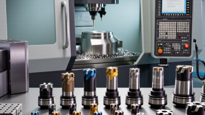
Choosing the right machining tools is rarely a simple matter of picking the hardest insert or the newest cutter. It begins with the workpiece, machine, tolerance, and production goal. A carbide end mill may perform beautifully in aluminum, yet struggle in hardened steel. A drill that survives one batch may produce burrs in another.

Tony Schmitz, a respected machining researcher and professor, has emphasized this practical principle: “The cutting tool is the business end of the machine tool.” That view keeps attention on the cutting zone, where heat, vibration, chip control, and tool wear decide the real result. The machine may be powerful, but poor tool selection can still leave a rough surface, a damaged edge, or an expensive rejected part.

This guide presents 10 tips for choosing machining tools with evidence, shop-floor judgment, and measurable details. It considers material hardness, tool geometry, coating, coolant, spindle speed, feed rate, and required surface finish. It also examines tool life, because the cheapest cutter is not always the lowest-cost choice. Sometimes a premium tool reduces downtime. Sometimes it does not.

Small details matter. A long tool overhang can amplify chatter. A dull drill can turn a clean hole into a tapered one. I have seen selection decisions fail because catalog data replaced actual testing. That mistake deserves attention.

The right answer may require a controlled trial, not confidence alone. These tips help connect specifications with real cutting behavior, while leaving room for review, adjustment, and better decisions.
10 Tips for Choosing the Right Machining Tools?

Define the Machining Task and Required Results

10 Tips for Choosing the Right Machining Tools

Define the Machining Task and Required Results

Choosing a machining tool starts with the task, not the tool catalog. Identify the material, feature, tolerance, surface finish, and production volume. A tool for rough stock removal may fail during precise finishing. Cutting hardened steel also requires different geometry from machining aluminum.

Tip 1: Measure the job clearly. Record hole depth, corner radius, wall thickness, and allowable variation. Small details matter.

Tip 2: Define the expected result. A ±0.01 mm tolerance demands more control than a general-purpose cut. In my experience, unclear requirements cause more tool changes than difficult materials.

Tip 3: Match the tool to the material. Consider hardness, abrasiveness, heat generation, and chip behavior.

Tip 4: Check machine limits before selection. Spindle speed, power, holder size, coolant access, and available travel can change the best choice. A technically excellent tool is still unsuitable if the machine cannot run it safely.

Run a controlled test when possible. Begin with conservative cutting data, then inspect chips, vibration, edge wear, and surface finish. Not every recommended setting works equally well in every workshop. I have seen a slower tool produce better results because the fixture was less rigid than expected. Record the outcome, including failures. That record becomes practical evidence for the next decision.

Match Tool Material and Geometry to the Workpiece

Choosing machining tools begins with the workpiece, not the tool cabinet. Identify its hardness, toughness, abrasiveness, and thermal behavior before selecting an insert or cutter. Hardened steel usually needs a rigid tool with wear resistance and a stable cutting edge. Aluminum often benefits from a sharper edge and wider chip space.

Geometry matters as much as material. A positive rake angle can reduce cutting force on soft metals, while a stronger edge suits tough alloys or interrupted cuts. Flute count also changes performance. Fewer flutes leave room for chips, especially during high-speed aluminum milling. More flutes may improve finish when the machine and workholding are sufficiently rigid.

Small details reveal poor choices. A long tool overhang can create vibration, even with excellent carbide. I have made this mistake. The surface looked acceptable at first, then showed regular waves after several passes. Reducing overhang solved more than changing the tool. Check cutting data against the actual machine, coolant method, and setup. Do not copy a catalog value blindly. Record spindle load, chip color, edge wear, and finished dimensions during a trial cut. These observations provide more reliable evidence than appearance alone. Reconsider the tool when heat builds, chips weld to the edge, or the workpiece begins moving.

10 Tips for Choosing the Right Machining Tools

Match Tool Material and Geometry to the Workpiece

The chart shows typical starting cutting-speed ranges for coated carbide tools when machining common workpiece materials. Softer materials generally allow higher speeds, while stainless steel and titanium require more conservative settings because of heat, work hardening, and low thermal conductivity. Final values should be adjusted for tool diameter, tool geometry, rigidity, coolant, and machine condition.

Select the Appropriate Tool Size, Coating, and Design

10 Tips for Choosing the Right Machining Tools?

Select the Appropriate Tool Size, Coating, and Design

Tool size controls cutting stability, clearance, and surface quality. Match the cutter diameter to the pocket, corner radius, and machine spindle. For a small pocket, an oversized tool may rub against the walls. A long tool can reach deeper areas, but it also deflects more easily. Measure the required depth before selecting flute length. Keep the shortest safe overhang.

Coating should match the workpiece and cutting conditions. Uncoated tools can perform well on soft aluminum and plastics. A heat-resistant coating is more suitable for hardened steel or high-speed cutting. Do not choose a coating by hardness alone. Coolant, chip evacuation, and cutting speed also affect tool life. In production trials, the wrong coating often shows as built-up edge or sudden chipping.

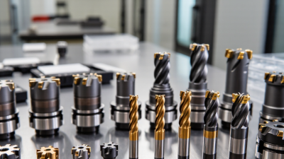
Tool design changes how forces move through the cut. A variable helix can reduce vibration during side milling. A higher flute count may improve finishing, but it leaves less space for chips. For deep pockets, fewer flutes may evacuate chips more reliably.

I once selected a long, fine-finishing cutter for a roughing pass. The finish looked acceptable, but the cycle time became excessive. That mistake was useful. Record tool wear, sound, chips, and measured dimensions after each test. Then adjust one variable at a time.

Check Machine Compatibility, Precision, and Cutting Conditions

Choosing the right machining tool begins with machine compatibility. Check the spindle taper, maximum rpm, available power, holder type, and coolant delivery. Confirm the tool diameter fits the work envelope. Then match the insert material and edge geometry to the workpiece. A sharp edge is not always better. Thin edges can chip during interrupted cuts. Shorter tool overhang usually improves rigidity and reduces vibration.

Precision requires measurable evidence. ISO 230-2 provides methods for testing positioning accuracy and repeatability. Use those results when selecting tolerances, not only the machine’s marketing specifications. Deloitte’s 2024 Smart Manufacturing and Operations Survey found that 92% of manufacturers view smart manufacturing as important for competitiveness. That finding supports using tool monitoring, spindle-load data, and inspection records. Still, digital data can mislead when sensors are poorly calibrated. Check the actual part.

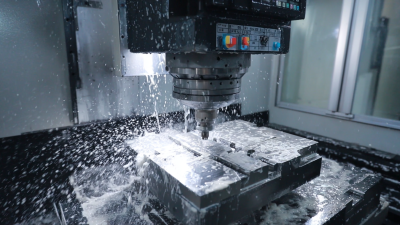
Cutting conditions deserve a controlled trial. Set speed, feed per tooth, axial depth, and radial engagement from the tool maker’s technical data, then adjust gradually. Watch the chip color, burr formation, surface finish, and spindle load. Excessive heat often signals speed, coolant, or chip-evacuation problems. Keep the toolpath stable. Measure tool life across several parts, because one successful cut proves very little. My own preference is a short test coupon before production, although this step is sometimes skipped under schedule pressure. That shortcut often costs more later. Record the final settings, including material batch, tool overhang, coolant concentration, and inspection results.

Compare Tool Life, Safety, Maintenance, and Overall Cost

10 Tips for Choosing the Right Machining Tools

Tip 1: Compare tool life under real cutting conditions, not only laboratory claims. Record edge wear after each batch. Tip 2: Check material compatibility with the workpiece. A tool that cuts hardened steel may perform poorly on aluminum. Tip 3: Measure surface finish regularly. Longer tool life means little if rework increases. Tip 4: Consider cutting stability. Excessive vibration can destroy an edge within minutes.

Tip 5: Review safety features before comparing prices. Secure clamping, heat control, and clear operating limits reduce workplace risks. Tip 6: Choose tools that support predictable chip control. Long, tangled chips create interruptions and possible injuries. Tip 7: Inspect maintenance needs carefully. Some tools require frequent cleaning, alignment, or coolant adjustment. That labor belongs in the calculation. Tip 8: Keep spare components available. A small missing insert can stop an entire shift.

Tip 9: Calculate overall cost, including downtime, setup time, consumables, and rejected parts. The cheapest purchase is often not the cheapest choice. Tip 10: Test tools on a controlled sample before full production. Record cycle time, wear, noise, and operator feedback. Experienced machinists know the spreadsheet can miss something. I have trusted early test results too quickly before. Recheck them. Also compare performance after several shifts, when heat and fatigue expose weaknesses. A practical decision balances tool life, safety, maintenance effort, and dependable cost.

10 Tips for Choosing the Right Machining Tools? - Compare Tool Life, Safety, Maintenance, and Overall Cost

Practical comparison of common cutting-tool choices under typical production conditions

Tip Selection Factor Recommended Tool or Practice Typical Tool Life Safety Considerations Maintenance Requirement Relative Cost per Part
1 Match the tool to the workpiece material Use coated carbide for general steels, carbide or ceramic for cast iron, and PCD for abrasive non-ferrous materials. 30–180 min Low risk when cutting data is within the tool maker’s limits. Inspect edges and verify tool offset after changes. Low–Medium
2 Prioritize tool life for long production runs Choose a wear-resistant coated carbide grade and use stable feeds, speeds, and depth of cut. 60–240 min Use guarded machines and stop immediately if vibration or unusual noise occurs. Scheduled wear checks every 15–30 min of cutting. Low
3 Select geometry for chip control Use chip-breaker inserts for continuous production and positive-rake geometries for aluminum and thin-wall parts. 45–180 min Effective chip breaking reduces entanglement and ejection hazards. Remove chip buildup and check coolant direction. Low–Medium
4 Consider cutting temperature Use coolant or minimum-quantity lubrication where appropriate; use ceramic tools only in stable, generally dry cutting conditions. 20–150 min Avoid thermal shock to ceramic tools and prevent coolant mist exposure. Maintain coolant concentration, filtration, and flow. Medium–High
5 Evaluate rigidity and vibration resistance Use a short, rigid toolholder, balanced assembly, and variable-pitch milling cutter for vibration-prone setups. 30–120 min Lower vibration reduces insert fracture and unexpected tool failure. Check holder runout; a common target is ≤0.01 mm for precision work. Medium
6 Choose the correct tool for surface finish Use a finishing end mill or wiper insert with a suitable nose radius; reduce feed per tooth for finer finishes. 40–160 min Prevent sudden edge chipping by avoiding excessive radial engagement. Measure roughness and replace tools before finish quality declines. Medium
7 Compare insertable and solid tools Use indexable tools for large material removal and solid carbide tools for small features, accuracy, and compact workpieces. Indexable: 60–240 min
Solid carbide: 30–150 min
Confirm insert seating and torque before operation. Indexable tools require insert rotation or replacement; solid tools require regrinding or disposal. Low–Medium
8 Account for setup and changeover time Select standardized toolholders and preset tools when frequent tool changes make labor a major cost. Not applicable Use a presetting station to reduce manual measurement near the machine. Clean taper surfaces and inspect holder condition before installation. Low over high volume
9 Calculate total cost, not purchase price Compare tool price, tool life, machining time, scrap risk, setup labor, coolant, and regrinding or recycling costs. Depends on application A predictable wear pattern is safer than occasional catastrophic failure. Track tool consumption, downtime, rejects, and maintenance events. Lowest total cost varies
10 Use tool monitoring and documented cutting data Record tool life, spindle load, vibration, surface finish, and failure mode; set replacement limits based on measured results. Often 10–30% longer
with optimized data
Early detection helps prevent breakage and workpiece ejection. Requires routine data collection and calibration of monitoring systems. Low after implementation
Data basis: Tool-life ranges are practical planning estimates for general CNC machining and can vary significantly with workpiece hardness, cutting speed, feed, depth of cut, machine rigidity, coolant, tool diameter, and operator practice. Relative cost ratings include tool consumption, downtime, labor, quality risk, and maintenance.
Scroll to Top