7 Brass CNC Machining Tips for Global Buyers

Buying precision parts across borders can feel simple until a brass component fails during assembly. A drawing may show a clean profile, yet tiny burrs, inconsistent threads, or incorrect alloy selection can create expensive delays. This is where practical brass cnc machining knowledge becomes essential for global buyers.

The seven tips in this guide focus on decisions that affect real production results. They cover alloy selection, tolerances, tooling, surface finish, inspection records, packaging, and supplier communication. A reliable manufacturer should explain how cutting speed, tool geometry, and heat control affect the finished part. Ask for material certificates, dimensional reports, and clear sampling procedures. Evidence matters more than confident promises.

Details often reveal process maturity. Look for protected threads, separated components, and packaging that prevents brass surfaces from rubbing together. Confirm whether dimensions are measured before or after finishing. That small question can expose a weak quality plan. However, no supplier is perfect. Even experienced teams can overlook a tolerance conflict or underestimate shipping risks. Good buyers leave room for technical review and corrective action.

These recommendations are designed for engineers, purchasing teams, and distributors managing international orders. They encourage practical checks before production begins, not after a shipment arrives. Read each tip with your drawings, inspection needs, and delivery conditions nearby. The best result is not merely a shiny brass part. It is a repeatable component that fits, performs, and arrives as expected.
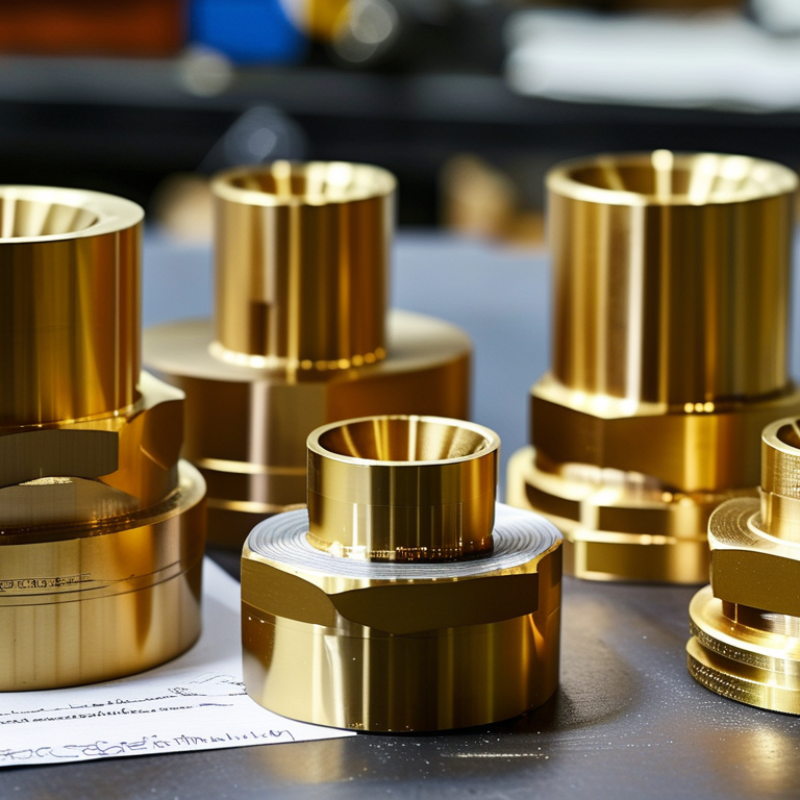
7 Brass CNC Machining Tips for Global Buyers

Identify C36000 Brass: 60–63% Cu and 2.5–3.7% Pb per ASTM B16

7 Brass CNC Machining Tips for Global Buyers

Identify C36000 Brass: 60–63% Cu and 2.5–3.7% Pb per ASTM B16

C36000 is a free-machining brass, not a generic yellow alloy. ASTM B16 specifies 60.0–63.0% copper and 2.5–3.7% lead. Zinc makes up most of the balance. This chemistry supports short, controlled chips and lower cutting resistance during CNC turning. It also creates a practical trade-off: lead improves machinability, but destination markets may restrict lead-bearing products. Confirm the customer’s requirements before production.

Do not rely on color alone.

Request a material test report linked to the heat or lot number. Check copper and lead values against ASTM B16, then verify diameter, straightness, and surface condition. The USGS Mineral Commodity Summaries 2024 reported approximately 22 million metric tons of mined copper production worldwide in 2023. That scale does not guarantee consistent bar quality. Traceability still matters.

On the shop floor, C36000 usually produces tight, curled chips when feeds and speeds are stable. A dull insert may smear the surface near a shoulder, even when the alloy certificate looks correct. Inspect the first-off part under bright light, especially around drilled holes and threads. I have seen purchasing teams focus heavily on composition and overlook chip evacuation. That mistake can increase cycle time and leave small burrs. Review the drawing, certificate, inspection report, and applicable destination rules together.

Match the Seven Tips to ISO 2768 Tolerances and Global Drawing Standards

Global brass CNC sourcing becomes safer when tolerance language is matched, not guessed. In production reviews, I use seven drawing checks to reduce avoidable disputes. Tip one is to state the ISO 2768 general tolerance class clearly. For example, ISO 2768-mK may control unspecified linear, angular, and geometric features. Do not assume the medium class suits every part. Tip two is to separate general tolerances from individually specified dimensions. That distinction prevents costly inspection disagreements.

Tip three is to confirm drawing units, decimal places, and revision status. Show millimeters or inches beside the title block. Tip four is to identify the governing interpretation standard, such as ISO 1101 or ASME Y14.5. Mixing datum symbols or feature-control methods creates uncertainty. Tip five is to define functional datums and inspection references. A hole position may pass ISO 2768 but fail its assembly purpose without a clear datum structure.

Tip six is to review brass-specific manufacturing risks. Thin walls can flex during clamping, while burrs can affect edge measurements. Specify deburring, surface finish, and thread requirements separately. Tip seven is to request a marked-up drawing before production. Include inspection methods, sampling expectations, and required reports. I have seen experienced teams overlook a tiny unit note. That mistake still deserves reflection. A practical review should compare the drawing, ISO 2768 limits, tooling capability, and measured results before approval.

7 Brass CNC Machining Tips for Global Buyers

Matching Practical Drawing Checks with ISO 2768 Tolerances and Global Standards

The chart shows representative bilateral linear tolerance limits from ISO 2768-1 tolerance class m for seven commonly reviewed brass CNC machining dimensions. The values are based on the nominal dimension ranges specified in ISO 2768-1 and are intended for general drawing review. Critical fits, hole locations, geometric features, threads, and surface requirements should be defined separately using applicable ISO 1101, ISO 129, ISO 286, or ASME Y14.5 requirements.

Optimize CNC Parameters Around C36000’s 100% Machinability Rating

7 Brass CNC Machining Tips for Global Buyers

Optimize CNC Parameters Around C36000’s 100% Machinability Rating

C36000 brass is valued for fast cutting and clean chip formation. Its 100% machinability rating is a useful benchmark, not a universal promise. The rating usually compares cutting behavior with a reference free-machining steel. It does not eliminate burrs, tool wear, or dimensional movement.

Set spindle speed, feed rate, and depth of cut as a connected group. A sharp carbide tool can support higher speeds, while a blunt edge may smear the brass surface. I often begin with moderate feed rates and inspect the first few parts. Then, I adjust speed in small steps. Small changes matter.

Control chips carefully. Long, stringy chips can scratch finished surfaces and create handling risks. High-pressure air or suitable coolant may improve evacuation, depending on the machine and drawing requirements. Secure workholding also matters, especially with thin walls. Excessive clamping can distort a part before cutting begins.

Leave enough stock for a light finishing pass. This can improve threads, bores, and sealing surfaces. However, too many passes may increase cycle time without improving accuracy. That judgment is easy to get wrong. Buyers should request material certification, measured inspection data, and the applicable dimensional standard. Specify surface finish, burr limits, thread gauges, and packaging expectations before production. A 100% rating helps plan parameters, but actual results still depend on tooling, machine rigidity, coolant, geometry, and operator experience.

7 Brass CNC Machining Tips for Global Buyers — Optimize CNC Parameters Around C36000’s 100% Machinability Rating
Tip Optimization Dimension C36000 Reference Data Practical Starting Guidance Reason and Expected Benefit Buyer-Side Quality Check
1 Confirm the material grade C36000 free-cutting brass is commonly specified with approximately 60.0–63.0% copper, 2.5–3.7% lead, and zinc as the balance. Its machinability rating is conventionally set at 100%. Require the material certificate to state the grade, temper, heat or lot identification, chemical composition, and applicable ASTM or equivalent specification before machining. C36000’s leaded composition supports short chips, lower cutting forces, and high production efficiency. Similar-looking brass grades may require different cutting parameters. Check the chemical report, temper designation, dimensional stock, and traceability documents against the purchase order.
2 Set cutting speed by tool material C36000 generally machines efficiently with carbide tooling. Cutting speed must be adjusted for tool geometry, machine rigidity, workpiece diameter, and operation type. Use approximately 150–300 m/min for carbide turning as a controlled starting window. Begin near the lower end for interrupted cuts, thin walls, or limited coolant performance. A stable speed range helps balance cycle time, edge life, surface finish, and heat generation instead of relying only on the 100% rating. Request the cutting-speed range, tool grade, insert geometry, and documented tool-life target used for production validation.
3 Match feed to chip control C36000 typically forms manageable chips, but feed selection still depends on tool nose radius, depth of cut, rigidity, and required finish. For carbide turning, a practical initial feed range is about 0.05–0.25 mm/rev. Use lower feed for fine finishing and higher feed only when rigidity and chip evacuation are adequate. Correct feed prevents rubbing, reduces burr formation, and supports consistent dimensional control without unnecessarily extending cycle time. Review sample-part chip form, burr height, surface roughness, and dimensional capability after the first production trial.
4 Control depth of cut and tool engagement C36000 is relatively easy to cut, but small parts and slender sections can deflect under clamping or cutting forces. Use a rigid setup and avoid excessive tool overhang. For finishing, reserve a consistent allowance of approximately 0.10–0.30 mm per side, then adjust after a trial cut. Predictable engagement improves roundness, concentricity, profile accuracy, and repeatability across multiple machining suppliers. Define datum strategy, clamping method, maximum tool overhang, and inspection points for runout, wall thickness, and concentricity.
5 Use positive, sharp tooling Free-cutting brass responds well to sharp tools with a positive cutting action. Dull or overly negative geometries can increase rubbing and burrs. Specify a sharp carbide tool suitable for non-ferrous alloys, polished rake faces where available, and a small controlled edge hone rather than a heavily honed edge. Positive geometry lowers cutting resistance and helps maintain clean edges, stable dimensions, and a bright machined surface. Ask for the tool material, rake or insert geometry, edge preparation, tool-change limit, and photographs of representative cutting edges.
6 Plan chip evacuation and coolant C36000’s lead content generally promotes chip breakage, but chip packing can still occur in deep holes, grooves, and high-volume turning. Use directed air or a suitable water-soluble coolant where required. For deep features, include pecking, chip-breaking cycles, or through-tool coolant according to machine capability. Effective evacuation protects the workpiece and tool, reduces scratching, and limits recutting of chips that can damage surface quality. Confirm coolant concentration control, filtration, chip-removal method, deep-hole strategy, and housekeeping requirements for export packaging.
7 Validate finish, burrs, and compliance Machinability does not automatically guarantee final part quality. Surface finish, tolerances, burr limits, cleanliness, and restricted substance requirements must be defined separately. Specify measurable requirements such as Ra, dimensional tolerances, burr height, visual acceptance level, cleanliness method, packaging, and inspection frequency. Validate with a first-article sample. Clear acceptance criteria reduce disputes between international buyers and suppliers and make production results easier to compare. Require a dimensional report, material certificate, first-article inspection record, surface-finish evidence, and lot-level traceability.
Parameter note: The cutting values above are practical starting ranges, not universal limits. Final settings should be validated on the actual machine using the selected tool, workholding method, stock condition, feature geometry, coolant system, and required tolerance. The 100% machinability rating is a comparative reference for C36000 and should not be treated as a guaranteed cycle-time or tool-life specification.

Verify Dimensions, Surface Finish, and Material Traceability Before Shipping

7 Brass CNC Machining Tips for Global Buyers

Before shipping brass CNC parts, request a dimensional report linked to the latest drawing revision. Measure critical bores, thread diameters, flatness, and hole positions with calibrated equipment. Do not accept “within tolerance” without actual readings. ISO 2768 supports general tolerances, but it cannot replace part-specific requirements. For tight fits, define the measurement method and inspection temperature. A 50 mm brass feature can change by roughly 0.01 mm across a 10°C temperature difference. That small shift can affect assembly.

Specify surface roughness using Ra values in micrometres, not vague terms such as “smooth.” Ask for readings from functional areas, especially threads, sealing faces, and sliding surfaces. Machining marks may look acceptable but still increase friction. ASTM B16/B16M can help verify suitable free-cutting brass grades and mechanical requirements. Yet visual inspection alone remains weak. I have seen attractive parts fail because burrs were hidden inside cross-drilled holes.

Material traceability needs equal attention. Request the heat or lot number, chemical composition, and mill certificate, preferably to EN 10204 3.1 requirements. The ISO Survey 2023 reported more than 1.26 million ISO 9001 certificates worldwide. Certification indicates a quality system, not automatic conformity for every batch. Cross-check the certificate against labels, packing lists, and test results. Handheld XRF screening is useful, but it cannot replace documented laboratory analysis. Leave room for doubt. A clean certificate can still describe the wrong material.

Compare Quotes Using MOQ, Lead Time, Incoterms 2020, and Total Landed Cost

7 Brass CNC Machining Tips for Global Buyers

Brass CNC machining quotes often look comparable until purchasing details are examined. My seven-check method starts with MOQ, because a low unit price can hide a large cash commitment. Ask whether MOQ applies per drawing, finish, or total order. Record sample quantities separately. A supplier may quote ten pieces, then require one hundred for production. That gap matters. Confirm material grade, tolerance, inspection method, and packaging before comparing prices. Unclear drawings create expensive assumptions.

Lead time needs two dates: production completion and dispatch readiness. Request a realistic schedule, including approval time, tooling, first-article inspection, and rework risk. “Ten days” is not enough. Ask what starts the clock. Incoterms 2020 then define cost and responsibility. Compare identical terms, such as FCA, FOB, or DAP, when suitable for the route. FOB generally suits sea or inland waterway transport. Check who handles export clearance, freight, insurance, import clearance, duties, and delivery. A cheap EXW quote may become costly after local pickup and paperwork. Verify the named place carefully.

Calculate total landed cost per usable part, not just the machining price. Include tooling, inspection, packaging, freight, insurance, duties, taxes, bank fees, and expected scrap. Request written evidence for material certificates, process controls, and inspection records. Keep every assumption in one comparison sheet. It will expose differences quickly. My own sheets are never perfect; currency changes and delays still disrupt forecasts. Recheck the numbers before approval, especially when a quotation looks unusually attractive.

Scroll to Top