
How to Choose the Right Small Travel Motor?

Choosing the right Small Travel Motor starts with understanding the machine, the terrain, and the work cycle. A motor that performs smoothly on a compact excavator may struggle on a tracked carrier. Weight, travel speed, torque, hydraulic flow, and operating pressure must match the manufacturer’s specifications. Do not choose by size alone. A small housing can still deliver strong torque, while an oversized unit may waste energy and increase installation stress.

Real field experience shows that working conditions often matter more than catalog figures. Mud, gravel, slopes, and frequent direction changes place different demands on the drive system. Check the reduction ratio, brake capacity, bearing strength, sealing quality, and port configuration. Ask for verified performance data, test records, and compatibility details from a qualified supplier. Service access matters too. A motor that is difficult to inspect can create expensive downtime, even when its initial price looks attractive.

There is no universal best choice. Not always.

Before purchasing, compare the motor’s continuous and peak ratings with your actual workload. Consider ambient temperature, maintenance intervals, replacement parts, and technical support. A careful selection process should include real operating measurements, not assumptions based only on advertising. Some specifications may look impressive but lack useful context. That deserves a second look. The right Small Travel Motor should provide controlled movement, dependable braking, efficient power use, and a reasonable service life for your specific equipment. Reliability is built through fit, evidence, and honest evaluation.
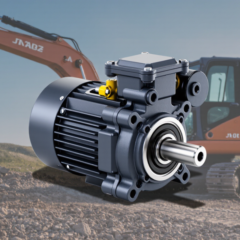
How to Choose the Right Small Travel Motor?

Define the Job: Mini-Excavator Motors Commonly Use 10–100 cm³/rev

How to Choose the Right Small Travel Motor?

For many mini-excavators, travel motors use 10–100 cm³/rev displacement. That range is broad. A 10 cm³/rev motor can support higher travel speed with limited hydraulic flow. A 100 cm³/rev motor produces more torque at the same pressure, but turns more slowly. Do not choose by displacement alone. Check the machine’s weight, track width, ground conditions, and expected travel speed.

Start with actual hydraulic data. Record pump flow, working pressure, relief-valve pressure, and available power. Motor speed depends mainly on flow and displacement. Torque depends on displacement, pressure, and mechanical efficiency. For example, a 50 cm³/rev motor at 30 L/min runs near 600 rpm before efficiency losses. In muddy soil, that speed may be less useful than stronger starting torque. That sounds simple. It is not always.

The reduction gearbox also changes the final result. Confirm its ratio, rated torque, shock capacity, and thermal limits. Check continuous and intermittent pressure separately. The case-drain requirement matters too. Excessive housing pressure can damage seals and bearings. A practical mistake is sizing for flat ground only. I have seen compact machines stall when one track climbs a wet slope. Leave a sensible torque margin, but avoid excessive displacement, which can waste flow and reduce travel speed. Field measurements are worth more than a catalog estimate. Recheck the choice after observing real loading.

Size Torque and Tractive Force with F = 2T/r in 20–35 MPa Systems

Choosing the right small travel motor begins with the machine’s real working conditions. In 20–35 MPa hydraulic systems, pressure alone does not determine performance. Motor displacement, mechanical efficiency, wheel radius, load, slope, and ground contact all matter. A compact motor may fit the frame, yet deliver too little torque for a wet incline.

The basic traction estimate is F = 2T/r. Here, F is ideal tractive force, T is wheel torque, and r is the effective wheel radius. For example, 1,200 N·m of torque with a 0.20 m wheel gives 12,000 N of theoretical force. Actual force will be lower. Rolling resistance, leakage, bearing losses, and tire slip reduce it. I have seen calculations fail because engineers used the unloaded radius instead of the loaded radius. That small mistake changes the result. Check both continuous and peak torque ratings, especially when the vehicle starts suddenly or carries a heavy attachment.

Tips: Measure the steepest route, not the workshop floor. Confirm pressure under flow, because pressure can drop during movement. Compare calculated force with required force, then keep a practical safety margin. A slightly larger motor may improve reliability, but it can also increase weight and cost. Recheck the choice after testing; field conditions often expose assumptions that looked reasonable on paper.

Match Hydraulic Flow to Speed with n = 1,000Q/V and 80–90% Efficiency

How to Choose the Right Small Travel Motor?

Match Hydraulic Flow to Speed with n = 1,000Q/V and 80–90% Efficiency

Selecting a small travel motor starts with matching hydraulic flow to the desired travel speed. Use n = 1,000Q/V, where Q is flow in liters per minute and V is displacement in cubic centimeters per revolution. For example, 12 L/min through an 80 cm³ motor gives an ideal speed of 150 rpm. Real machines operate below this figure. With roughly 85% volumetric efficiency, practical speed may be about 128 rpm. Check the technical data carefully. Efficiency varies with pressure, temperature, wear, and oil condition.

Speed alone does not prove the motor is suitable. Confirm available pressure, required wheel torque, machine weight, slope, and duty cycle. A compact loader moving across wet ground may need more torque than its normal travel speed suggests. My first calculation is often too optimistic. Field testing can reveal heat buildup, weak starting torque, or unstable low-speed movement. These details matter more than a neat formula.

Tips: Measure actual flow at the motor inlet, not only the pump rating. Keep a small safety margin below maximum continuous speed. If speed is too high, reduce flow or select greater displacement. If torque feels weak, check pressure and load before increasing flow. Remember that 80–90% is a working estimate, not a permanent constant. Record oil temperature during testing. Small errors become obvious on long travel cycles.

Select Gearing, Brakes, and Controls for Slopes and Shock Loads

How to Choose the Right Small Travel Motor?
Choosing a small travel motor starts with the terrain, not the catalog speed. A 12-degree slope can demand much more torque than level ground. Estimate total machine weight, rolling resistance, slope angle, and acceleration before selecting gearing. Keep a safety margin for mud, loose gravel, and uneven tracks. A motor that feels powerful indoors may struggle outdoors.

Gearing should provide steady tractive force without forcing the motor beyond its thermal limits. Lower gearing improves slope control, but it reduces travel speed. For frequent stops, select a spring-applied, hydraulically or electrically released brake with enough holding torque for the full loaded machine. The brake must hold on a slope, not merely slow the motor. Check stopping distance under wet and cold conditions.

Small details matter.

Controls should match the operator and the work cycle. Proportional control gives smoother starts and reduces shock loads on gears, axles, and tracks. Ramp settings can prevent sudden torque spikes when reversing. Pressure relief and current limits also protect the drivetrain during a jam. Test the motor with realistic loads, including short impacts and repeated direction changes. Do not trust one clean workshop test. Field conditions often expose mistakes. I would also recheck the calculation after adding tools, guards, or attachments, because “small” weight increases can change the result.

Verify 10–20 μm Filtration, ISO 4413 Safety, and Mounting Compatibility

Choosing the right small travel motor starts with hydraulic cleanliness, not catalog size. In field inspections, a compact motor may lose smooth travel after one contaminated cycle. Verify filtration between 10 and 20 μm. Confirm whether the rating is nominal or absolute. That difference matters. Ask for test data, service intervals, and fluid cleanliness requirements. A pressure gauge near the filter can reveal rising restriction before movement becomes jerky. I have seen operators blame the motor when a neglected return filter caused the real problem. Filtration cannot remove water from damaged oil.

ISO 4413 should guide the safety review. Check pressure relief, hose ratings, emergency isolation, and protection from stored hydraulic energy. The system should prevent unexpected movement during inspection or maintenance. A qualified technician should verify the circuit, especially when the motor works near people or heavy loads. Do not rely on a certificate alone. Installation details matter.

Mounting compatibility deserves equal attention. Measure the shaft, flange, bolt pattern, pilot diameter, port position, rotation, case-drain needs, and available space. A two-millimeter mismatch can create vibration or leakage. Compare the motor drawing with the actual machine, not an old file. My checklist is useful, but it is not flawless. I still recheck measurements after removing guards, because hidden spacers and worn holes often change the installation picture. A careful trial fit can prevent an expensive redesign.

How to Choose the Right Small Travel Motor? - Verify 10–20 μm Filtration, ISO 4413 Safety, and Mounting Compatibility

Selection Dimension Recommended Target Why It Matters What to Verify Before Purchase Status
Hydraulic circuit type Closed-loop or open-loop motor matched to the machine circuit A motor designed for the wrong circuit may have incorrect flushing, case-drain, or control requirements. Confirm the circuit diagram, charge-pump arrangement, valve configuration, and required case-drain connection. Required
Displacement Typically 10–50 cm³/rev for compact travel applications; size from load and speed requirements Larger displacement produces more torque at the same pressure but reduces speed at a given flow rate. Use: speed ≈ flow × 1,000 ÷ displacement, with speed loss allowed for volumetric efficiency. Size carefully
Continuous operating pressure Select a continuous rating above the machine's maximum sustained pressure; many compact units operate around 160–250 bar Continuous pressure affects service life, heat generation, shaft loading, and seal durability. Compare the motor's continuous, intermittent, and peak pressure ratings with measured system pressure, not only the relief-valve setting. Required
Torque requirement Choose a motor whose continuous and starting torque exceed the calculated wheel or track torque Starting, climbing, braking, and obstacle conditions can require substantially more torque than steady travel. Approximate theoretical torque: T ≈ 0.0159 × pressure (bar) × displacement (cm³/rev) × efficiency. Add a suitable safety margin. Calculate
Operating speed Select a rated speed range that covers both minimum maneuvering speed and maximum travel speed Excessive speed may cause heat, noise, cavitation, or premature bearing and seal wear. Check minimum stable speed, maximum continuous speed, flow range, acceleration behavior, and braking requirements. Required
Filtration cleanliness 10–20 μm nominal or absolute filtration, selected according to the motor manufacturer's cleanliness requirement Contamination can damage precision surfaces, valves, bearings, and seals, especially during frequent reversing. Verify filter micron rating, β-ratio or efficiency data, dirt-holding capacity, bypass setting, and required ISO 4406 fluid cleanliness code. 10–20 μm verify
Hydraulic fluid Use a compatible mineral-based hydraulic fluid or an approved alternative within the specified viscosity range Incorrect viscosity or fluid chemistry can reduce lubrication, increase leakage, and damage elastomers. Confirm fluid type, viscosity limits, temperature range, additive compatibility, and seal material with the technical datasheet. Required
ISO 4413 safety compliance System design and installation aligned with ISO 4413 hydraulic safety principles Hydraulic energy can remain stored after shutdown and can cause unexpected movement or injection injuries. Verify pressure limitation, safe isolation, discharge of stored energy, hose protection, guarding, emergency-stop behavior, and maintenance access. ISO 4413 verify
Mounting compatibility Exact match for flange, pilot diameter, bolt pattern, shaft, and rotational direction A dimensional mismatch can create misalignment, excessive side load, leakage, or installation failure. Compare certified drawings for mounting face, pilot fit, bolt-circle dimensions, bolt grade, shaft diameter, spline or key profile, and port orientation. Must match
External loads and bearing capacity Use a motor with sufficient radial and axial load capacity, or provide an external support bearing Direct wheel, sprocket, or belt loads may exceed the motor bearing capacity even when torque is adequate. Check radial-load direction and distance from the mounting face, axial load, overhung load limits, and duty cycle. Required
Temperature and heat rejection Keep fluid and housing temperatures within the motor's published operating limits; commonly target fluid temperatures below approximately 80°C unless specifically rated higher High temperature accelerates oxidation, seal aging, viscosity loss, and component wear. Evaluate ambient temperature, duty cycle, leakage losses, cooler capacity, airflow, and temperature measurement location. Check application
Noise, vibration, and installation Use rigid alignment, correctly sized hoses, and vibration isolation where necessary Air, pressure pulsation, pipe strain, and misalignment can increase noise and shorten service life. Verify hose size, minimum bend radius, port torque, suction conditions, air-bleeding procedure, and allowable vibration level. Inspect during installation
Testing and maintenance Establish commissioning checks and periodic inspection intervals based on operating severity Early detection of leakage, contamination, overheating, and abnormal noise helps prevent unplanned downtime. Record pressure, speed, temperature, leakage, vibration, filter condition, and fluid cleanliness during commissioning and service. Recommended
Selection note: The pressure, speed, displacement, temperature, and filtration values are general engineering targets rather than universal ratings. Always confirm the final motor selection against the manufacturer's certified performance curves, installation drawing, fluid specification, and the complete machine risk assessment.
Scroll to Top